Home › Guides › Laser kerf test: measure it, then set it once
Laser kerf test: measure it, then set it once
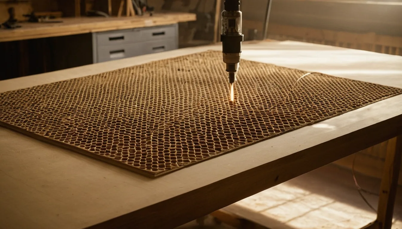
Kerf is the width of material the beam removes, and it differs by machine, material, focus and speed. Measure it on your own material, enter it in one place only, and fitted parts stop being a lottery.
What kerf is, in one paragraph
The beam has width, so a cut is a thin channel, not a line. Parts cut on their outline finish about one kerf smaller than drawn and holes finish about one kerf larger. The maths and a fit chart live in our kerf calculator, and laser-cut joinery that actually fits shows how it plays out in finger joints. This page is the other half: how to get the number.
The simple test: cut a square, measure it
- Draw a 20 mm square and cut it from the material and thickness you will actually use, at the settings you will actually use.
- Measure the part with calipers, in a couple of places.
- Subtract: the difference between drawn and measured is your kerf. As an example from our calculator page, a 20 mm square that measures 19.85 mm means 0.15 mm of kerf. That is a worked example, not a typical value for your machine.
Measure the part, not the hole it leaves, and use a closed shape. LightBurn documents that Kerf Offset only applies to closed shapes.
The more precise test: LightBurn's kerf offset test
LightBurn publishes a guide for this (Test Kerf Offset). The workflow it describes: set the layer's Kerf Offset to 0, run its Vernier-style kerf test file, read which pair of marks lines up, and enter that value in the Cut Settings Editor. It also suggests saving the value to the Material Library. Its docs add a tip for beams of irregular shape: run the test at a 45 degree angle and cut parts at that same angle. Check the guide for the version of LightBurn you run, because the 2.0 and 2.1 docs describe slightly different tools.
Community reports say the vernier result can be ambiguous between two marks, and that a finger-joint test can give a different answer than a plain rectangle. Treat the number as a starting point and confirm with a real joint.
What changes your kerf
Your kerf is not a property of the machine. It moves with:
- Material and thickness. Re-measure when either changes. Our calculator says kerf grows with power and stock thickness.
- Focus. A beam out of focus is wider. See how to focus a laser; a focus error also shows up as a tapered cut edge.
- Speed and power. The cutting speed guide covers how they interact.
Our calculator quotes a typical 0.1 to 0.2 mm on a CO2 laser. Diode kerf, set by a different spot shape, is something to measure yourself rather than copy from a table.
Where to enter it, and why only once
Put the correction in one place: either in LightBurn's kerf offset on the cut layer, or in your design tool, or in your drawn dimensions. A third-party LightBurn guide warns that applying compensation in both a design tool and LightBurn can leave joints too tight. Write down which tool owns kerf for each file.
Test with a real joint before a production run
Cut a small box joint or a press-fit slot at your measured kerf, check the fit, and adjust in steps of a few hundredths of a millimetre. When you change material, repeat the test on that material, or run a test grid as part of the same pass.
FAQ
What is a typical laser kerf?
Our kerf calculator quotes typically 0.1 to 0.2 mm on a CO2 laser. It changes with material, thickness, focus, speed and power, so measure your own.
How do I measure laser kerf?
Cut a closed square of a known size, such as 20 mm, in your real material and settings, then measure the part with calipers. The difference between drawn and measured size is the kerf: a 20 mm square that measures 19.85 mm means 0.15 mm.
What is LightBurn's kerf offset test?
A test file in LightBurn's documentation. Set Kerf Offset to 0, cut the test, read which marks align, and enter that value in the Cut Settings Editor. Check the guide for your LightBurn version.
Does kerf offset work on open lines?
No. LightBurn's documentation says Kerf Offset only applies to closed shapes.
Why are my joints too tight after kerf compensation?
A common cause is compensating twice, once in the design tool and again in LightBurn. Apply the correction in one place only.